 Choose
an appropriate beam length: for instance, 32" for an iron or 38" for a
wood. Place the club in the NF4, with the clubhead close to the tip
stop. But be sure that the club only touches the NF4 where the bearings
touch the shaft; if there is any interference between the NF4 and the
clubhead or ferrule, move the club to give more clearance.
Choose
an appropriate beam length: for instance, 32" for an iron or 38" for a
wood. Place the club in the NF4, with the clubhead close to the tip
stop. But be sure that the club only touches the NF4 where the bearings
touch the shaft; if there is any interference between the NF4 and the
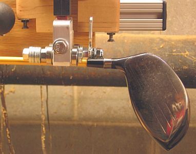
clubhead or ferrule, move the club to give more clearance.I usually position the club with the top of the ferrule even with the tip stop, as shown in the photo. That is close enough to give good results, and generally eliminates any problem with clearance.
 Don't
worry if the the back bearings rest on the grip instead of bare shaft.
Theoretically, this could result in a less stiff reading than the
actual shaft. But in practice, the error is less than 0.04Kg, so it can
be ignored.
Don't
worry if the the back bearings rest on the grip instead of bare shaft.
Theoretically, this could result in a less stiff reading than the
actual shaft. But in practice, the error is less than 0.04Kg, so it can
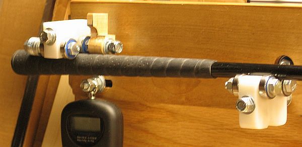
be ignored.The grip does present a more troublesome problem: placing the club in the bearings. That's because the grip does not slide in the bearings the way a shaft does.
The best way to deal with this is to position the head end close to the correct position before you insert the club into the bearings. Then set it into the rear bearings first, and work the head end into the front bearings . That way, you minimize having to slide it. But you probably will have to slide it a little, perhaps up to an inch. Here's how. Hold the rear bearing block to keep it from rotating, while your other hand relieves the pressure between the grip and the rear bearings. You can master this with a little practice.
(Yes, you could remove the grip for the measurement. But, once you have mastered the technique of placing the club, it is much easier than removing and replacing the grip.)
If the digital scale on your NF4 is not on at this point (because you forgot to turn it on, or because the auto-off kicked in while you were positioning the club), you will have to turn it on. It is possible that the added diameter of the grip will provide enough load so the scale will refuse to turn on. If so, press down on the rotator board to take pressure off the scale while it turns on.
Now take a reading of the stiffness of the shaft. It should be repeatable to 0.03Kg or better. Record the reading, since it will be the target load for the new club.
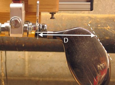
Without moving the club from the position where you took the stiffness reading, measure the distance from the tip stop to the ground line of the club. This measurement, shown in the photo, is taken along the centerline of the shaft. Call this distance D.
Why do we measure D? The club's flexibility depends on the distance from some reference point on the shaft to where the centerline of the shaft would meet the ground. We are going to make sure this is what we match.
 Place
the new shaft in the NF4 with the tip extended, and dry-fit the new
clubhead on the tip. It is not necessary that this be a tight fit; in
fact, a tight fit is probably undesirable. Carefully slide the assembly
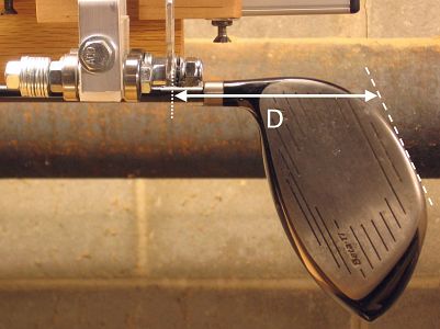
in the bearings until it has the same D measurement as the existing club. Be sure that the shaft is still properly bottomed out in the hosel.
Place
the new shaft in the NF4 with the tip extended, and dry-fit the new
clubhead on the tip. It is not necessary that this be a tight fit; in
fact, a tight fit is probably undesirable. Carefully slide the assembly
in the bearings until it has the same D measurement as the existing club. Be sure that the shaft is still properly bottomed out in the hosel.Temporarily mark the shaft, using the tip stop as a marking guide. (A washable marker or a scrap of masking tape will do fine here.)
 Carefully
remove the head from the shaft, making sure that the shaft stays in the
same position in the bearings. If it slides forward or back in the
bearings, you have your temporary mark so you can replace the shaft as
it had been.
Carefully
remove the head from the shaft, making sure that the shaft stays in the
same position in the bearings. If it slides forward or back in the
bearings, you have your temporary mark so you can replace the shaft as
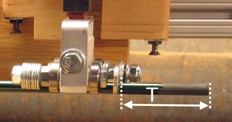
it had been.Measure the distance from the tip stop to the tip of the shaft. Record that distance as T.
Alternatively -- and more simply -- you can remove the assembly from the NF4, remove the clubhead from the shaft, and measure the distance from the temporary mark to the tip as T.
Once you have recorded T, you can discard the temporary mark.
At this point, you want to find the position of the shaft that gives the same target load that you measured for the original existing club. You can find it purely by trial and error, or you can use the spreadsheet to give you an estimated trim.If you use the spreadsheet, use the page labeled "Woods".
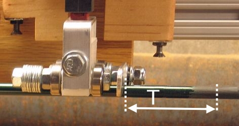
Once you have found the position that gives the target load, leave the shaft in the NF4. As the photo shows, measure the distance T (the same T you measured before) to the right of the tip stop. Mark and trim the shaft there.
Now simply prep the tip and build the club.